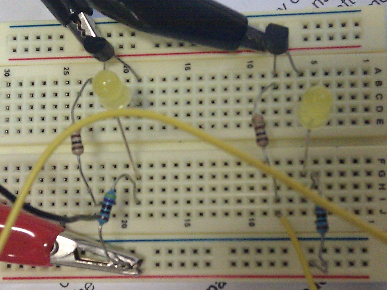
The first component we studied in this course was resistors.Resistors resist the flow of current.The higher the resistance,the lower the current.Resistors are colour coded.Resistors restrict the flow of current,for example;a resistor placed in series with a light emitting diode(LED)to limit the current passing through the LED.

Resistors can be used as voltage dividers to get a lower voltage at a certain point in the circuit than the input voltage of the circuit.The voltage gets divided according to the resistance in the circuit.
Resistors are used with transducers to make sensor sub-systems.Transducers are electronic components which convert energy from 1 form of energy to another. Resistors can be connected either way round.They are not damaged when soldering(not too hot).The resistor values are given in the form of bands.Each colour represents a number.There is a chart to get the values of the resistors

- The 1st band gives the 1st digit
- The 2nd band gives the 2nd digit
- The 3rd band indicates the number of zeros
- The 4th or 5th band is used to show the tolerance of the resistors.The tolerance is the precise measurement of the resistor.
silver +/-10% ,gold+/-5?% ,red+/-2%,+/-1% brown
Resistors are hooked up either in parallel or in a series setup in a circuit.

(A parallel and series circuit)
- Resistors In Series
- Resistors In Parallel
Last year we did a project at work for the Automotive Expo in USA.We used a Toyota 2KD alternator to get higher output.The original output for these alternators is 130 Amps.We stripped the alternator down.The stators in these alternators are originally winded up in parallel.We used the same stator but hooked it up in series.Assembled the alternator back.Tested the alternator on the biggest test bench in the workshop.(This machine could take readings of up to 270Amps).And the results were amazing...The output was 270 Amps.It could have been higher but the machine could only take readings up to 270.That was something new to all of us in the workshop.Very high current was good.But the downside is that such high currents cannot be supplied by the alternator for long periods,as that will melt the rectifier.That proves how efficient these parallel and series connections are......
We studied diodes as well.A diode is an electronic version of a check-vavle.It is used to convert AC current to DC current.Just as used in the alternator rectifier.It allows electric current to pass in one direction and blocks the current to return back.A diode has a characteristics of an insulator when current tries to flow in 1 direction.And a diode acts as a conductor when current flows in the other direction. Diodes must be connected the correct way round,the disagram shows (a or +) for the anode and (k or -)for the cathode.Diodes are labelled with their code,which is written in very small print.Diodes must be soldered with care,as they get damaged by heat when soldering.Rectifier diodes don't need special precautions when soldering.Can use a multimeter to test diodes.Energy is used by the electricity to push it's way through a diode.This is foward voltage drop.It is about (0.6V).All diodes have a maximum reverse voltage-around 50V or more-and if this voltage is exceeded,the diode will fail and pass a large current in the reverse direction.This is the breakdown..Ordinary diodes can be split in 2 types=>Signal diodes pass small currents of 100mA or less and Rectifier diodes can pass large currents.Diodes are doped by changing the behaviour of silicon and turning it into a conductor.In doping,a small amont of impurity is mixed into the silicon crystals.Doping gives a material it's semi-conducting properties.If you don't dope it,it's more or less an insulator.

We also studied ZENER diodes.These diodes are like the normal diodes but they also have a special characteristic.They work as the other diodes,but allow current to pass back when a certain voltage is reached(breakdown voltage).Zeners are used to maintain a fixed voltage.They are designed for breakdown voltage in a reliable and non destructive way so that they can be used in reverse to maintain a fixed voltage across their terminals.Zeners can be differentiated from other diodes by their code and the breakdown voltage which the manufacturer prints on the diodes.Zener diode code begin with BZX...........or BZY....................Their breakdown voltage is printed with V in place of a decimal point.eg:5V8 =>5.8V
Zeners are rated by the breakdown voltage and maximum power.
- The minimum voltage available is 2.4V
- Power ratings of 400mW and 1.3W are common.


We used resistors in our injector circuit and the oxygen sensor display circuit.Also used diodes in the oxygen sensor display circuit.

(4-pin relays)

(100W spotlight wiring)

(circuit using a switch,relay,bulbs)


We did some diagrams of circuits using relays to operate components,like motors and lights.Relays can be used to control a high -voltage circuit with a low -voltage signal.Can be used to control a high-current signal.eg.boosting current supply to the starter solenoid.Can be used for opening and closing circuits.And can also be used as circuit breakers.Relays simplify circuit wiring.Applications where long wires are used,eg boats,relays are required to compensate for the voltage drop.
We had a couple of wiring diagrams.Did a ford and subaru lighting wiring diagram in depth.The subaru wiring diagram was quite different.There was heaps of wires.Saw how the power is supplied from the ignition switch.Hot all times=>constant power to unit or wire(main).Power goes to fuse box=>fuse will blow if there is short circuit.Left headlight relay,Right headlight relay,Front Fog lamp relay,daytime running relay,all the wiring to these relays,some cases the power source was going to some other unit(indicated by the break lines).Units not shown in some cases.Also saw how the power is supplied to the park brake warning indicator,and the 3 wires going to the head light bulbs=>high beam low beam and the grounding(-).Now we know how to trace the wires on a wiring diagram and know what process the power goes through before reaching the bulbs.The wiring diagram clearly indicates how the combination switch and the daytime running light control module works.
The Ford diagram was much simplar.Also because we had already seen a much more complicated wiring diagram.In the ford lighting system we learnt how the ford day and night sensor woks,the connections to it, the power source.Wires that were hot all times(constant power+),hot in run or start(ignition power),hot in Acc or Start(Acc or Ignition power),and where the bulbs are grounded.Saw the dimmer switch,lighting control module,how these divert power to the different units for different functions.
Did theory and practical on Op-Amps.The op-amps amplify signals

(Op-amp pictures)
An op-amp is a devise that compares 2 voltages or currents and switches it to output to indicate which is larger
Op-amps ars very widely used today.An op amp is a device that compares 2 voltages or currents and switches it output to indicate which is larger.Op amps have a high gain.The op amps output voltage is limited by the supply voltage (voltage at the rail).
When the non-inverting input(V+)is at a higher voltage than the inverting input(V-),the high gain of the op amp causes the output to saturate at the highest positive voltage it can output.When the non-inverting input(V+)drops below the inverting input(V-),the output saturates at the most negative voltage it can output.The op amps output voltage is limited by the supply voltage.Many op amps have back to back diodes between their inputs
(Diagrams from www.opamp.electronics.com/)


 (Intercom circuit)

MOSFETS=>Metal Oxide Semiconductor Field Effect Transistor
(Diagrams from www.opamp.electronics.com/)


MOSFETS=>Metal Oxide Semiconductor Field Effect Transistor
There are 2 types.Depletion type requires the Gate-Source voltage to switch the device''OFF''.The depletion mode mosfet is equivalent to a ''NORMALLY CLOSED'' switch.The Enhancement Type requires a Gate-Source voltage to switch the drive ''ON''.The enhancement mode mosfet is equivalent to a''NORMALLY OPEN''switch. Mosfets are electrically insulated from the main semconductor N-channel or P-channel by a thin layer of insulating material usually silicone dioxide(commonly known as glass)Mosfets are useful for high speed switching applications and also on integratedcircuits in computors.Mosfets are a comoon type of transistor in which charge carriers such as electrons flow along channels.The width of the channel,which determines how well the device conducts,is controlled by an electrode called the gate,which is separated from the channel by a thin layer of oxide insulation.This insulation keeps current from flowing between the gate and channel.Line in Mosfet means it's in depletion mode.The breaks mean it's in enhanced mode.
The Gate terminal may be thought of as controlling the opening and closing of a physical gate.The gate permits electronsflow through or blocks their passage by creating or eliminating a channel between the source and the drain.Electrons flow from the source terminal towards the drain terminal if influenced by an applied voltage.
The Gate terminal may be thought of as controlling the opening and closing of a physical gate.The gate permits electronsflow through or blocks their passage by creating or eliminating a channel between the source and the drain.Electrons flow from the source terminal towards the drain terminal if influenced by an applied voltage.
All electronic units use heaps of tiny components,ie,diodes,resistors,capacitors,LED's,relays,micro relays,transistors,op-amps and other little components.We have to know what each individual component is and how they operate.Now after studying most of these components individually,we know how the components behave in a circuit and what they do.We have also done 2 projects(The injector circuit and the oxygen sensordisplay unit) and have used most of the components we studied.Now it wil be very simple to follow wiring diagrams and to identify and diagnose a fault in a electronic unit