INJECTORS
Today,over 95% of all cars produced are EFI equipped.EFI is certainly not new.It was established over 25 years ago.EFI uses solenoid valves called INJECTORS for the fuel delivery, and most of today's cars use one injector per cylinder.Fuel sprays out of the valve port when the solenoid is energised.The fuel is supplied to the injector by a high pressure electric pump,(fuel pump). The longer the injector is open,the more the fuel is injected.As the engine load and RPM are increased,the injector open times are increased to match increasing airflow.This is achieved by the electronic ECU.The computer(ECU) output signal is called the injecter pulse width.The longer the pulse width,the more the fuel is injected. The vehicle then accelerates.Some high performance cars have the original ECU modified(re-chipped)to get better performance.These cars then can keep on accelerating and going at maximum speed and the ECU doesn't cut off to slow the vehicle.


 Picturesfrom:forgedperformance.com
http://www.amsperfofmance.com/
CIRCUIT BOARD COMPONENT LIST
- Max Current 1A@75degrees celcious
- Max Pd=2.5Watts
- Max reverse voltage=100V
- Saturation Voltage-5mA
R=V/R R13=880Ohms
=4.40/0.005 R14=500Ohms
=880 Ohm R15=500Ohms R16=100 Ohms,4.4V
R=V/I
R=10/0.02 LED 1} 1.8V 20mA R14=10V LED 2}1.8V 20mA
=500Ohms 5V-0.6=4.4V R15=10V
R14=4.4V
Voltage Input =12V(+).
Ic Vce Vbe
100Ohms 44mA 5.37V 0.45V
1000Ohms 5.33V 0.43V
10K/Ohms 5.25V 0.41V
1M/Ohm 10.22V 0.35V
13 Ohms 5.32V 0.44V
Base to Emitter
4.55V 4.5V
Available voltage at some points (Usiong multimeter)
(1)7.22V
(2)5.21V
(3)0.44V
Frequency:0.05=14mA Frequency:2.5=7mA(FULLY ON)
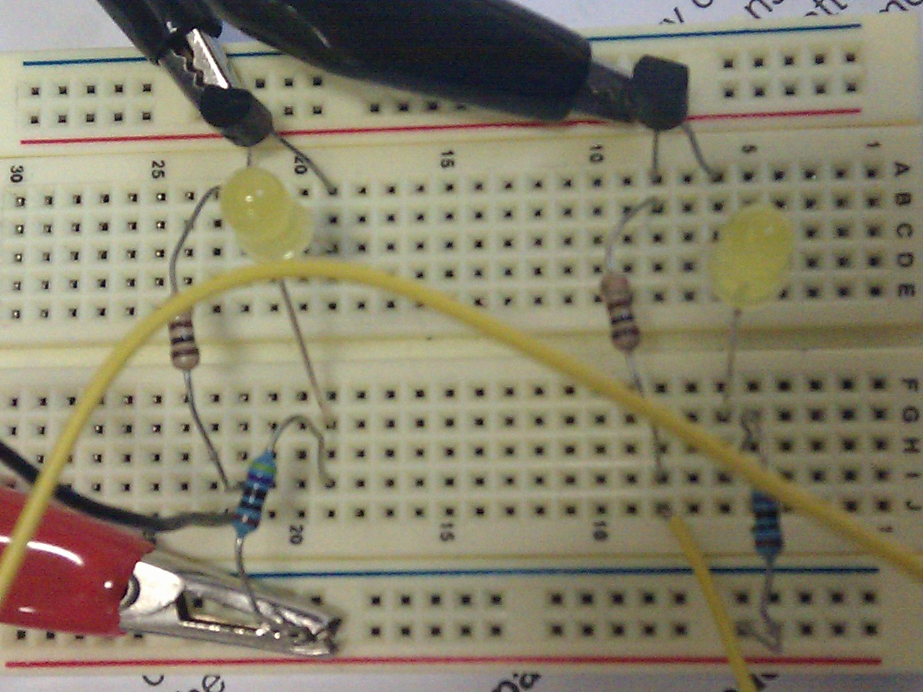
Made sample on a small bread-board.Got the circuit done.tests were done.Then i tried another LED in my circuit.Now i had 2 LED's and different colours.circuit was working.But i did notice that the brightness of the 2 LED's were not the same.Green looked brighter then yellow.And the frequency on the yellow looks slower.Checked the circuit to make sure everything was ok.All the connections were good.Must be something with different coloured LED,s.Tried a red LED as well.Red doesn'tl look as bright as the green LED.Green looked to be the brightest and fastest.Seemed like an optical illusion!I had tried green,red and yellow LED'S.
Used green in the final circuit
If the voltage is reduced to 6V,the LED's still work.But not as bright


PROCEDURE FOR BUILDING FINAL CIRCUIT
I downloaded Lochmaster Version 4.0 Demo.It took about 6 minutes to download.Took me a while to get used to the lochmaster program.Couldn't get the right bread-board.Managed to find the right bread-board got it to required size(30x50).Then started making my injector circuit on the lochmaster.Took me about 2 hours toproperly get it done.Got the bread-board checked and eventually got the approval.Then got the required bits to make my circuit.Managed to solder the pieces in the same class.Tested the circuit.All was ok.Powered the circuit.Both the LED's were working.Changed the frequency.LED's started blinking faster.That shows that as you accelerate,the pulse from the ECU increases,therefore the injectors operate faster.Showed my circuit to my lecturer,he said the circuit was ok.And said that i could even use 2 different frequencies.Tried it and it was really interesting to see the LED's operating at different intervals and speeds.Just as the vehicle ECU sends signals to the different cylinders at different intervals
WIRE COLOURS ON MY CIRCUIT
*RED wire=12V(+),BLACK wire (-),YELLOW wire and GREEN
wire(Frequency Generator) >both for the positive frequency generator signal


- Got some readings of the circuit.It was still powered up.The readings were fluctuating because the LED;s were ON.And at different frequencies the results were not stable.
- LED's flashing at about 600 times per/minute
- FREQUENCY 3.0 LED;s operating really fast.Seems like it's ON
- FREQUENCY 2.5 LED's pulsating really fast
- FREQUENCY 2.0 Pulsating fast
- FREQUENCY 1.5 Flicking at medium rate
- FREQUENCY 1.0 Flicking at a slow rate
- FREQUENCY 0.1 Flicking really slow at longer intervals
- FREQUENCY 0.05 Flicking very slowly.LED's very bright.Long intervals
- Range of 1000Ohms LED's ON on all frequencies from 0.05 to 3.0
- Range of 10 Ohms Flicking very fast
- Range of 100Ohms
- FREQUENCY 0.05 Flicking slowly and lights are bright
- FREQUENCY 0.1 Flicking very fast
- FREQUENCY 1.O ON constantly
- FREQUENCY 1.5 ON constantly
- FREQUENCY 2.0 ON constantly
- FREQUENCY 2.5 ON constantly
- FREQUENCY 3.0 ON constantly
REFLECTION
If i had the opportunity to do this circuit again,i would use 4 LED,s in my circuit.And use different coloured LED's.Would make 4 individual circuits.And after the circuits are done,i would hook each individual circuit to a different frequency generator.And with the different frequencies i would arrange it in 1-3-4-2 order.Just like a 4-cylinder engine.Would be really good to see how the LED's behave at a frequency of 800rpm.
From this experiment i have learnt how an injector operates at different frequecies.I could actually control the whole circuit. And now i know how the injectors react as the vehicle is accelerated.As you accerate,the signal sent from the car ECU increases,therefore increasing the intervals at which the injectors open and close.
,m,kknnnl;/'kp}
n
Better than your previous blog.I would change the background colour because its hard to read the writing. Try work on putting headings & structure to your blogs
ReplyDeletePlaytech signs partnership with Bovada. Online casino
ReplyDeleteBovada.lv, an 제왕카지노 online gambling company, has 온카지노 signed a deal with Bovada for a sports betting solution for 바카라 사이트 the company's players.