SENSORS

In order to provide the correct amount of fuel for every operating condition,the engine control unit(ECU) has to monitor a huge number of input sensors.Here are just a few:
- Mass airflow sensor -Tells the ECU the mass of air entering the engine
- Oxygen sensor(s)-monitors the amount of oxygen in the exhaust so the ECU can determine how rich or lean the fuel mixture is,and make adjustments accordingly.
- Throttle position sensor-monitors the throttle valve position(which determines how much air goes into the engine) so the ECU can respond quickly to changes,increasing or decreasing the fuel rate as necessary.
- Coolant temperature sensor-Allows the ECU to determine when the engine has reached it's proper operating temperature.
- Manifold Absolute pressure sensor-Monitors the pressure of air in the intake manifold.
- The amount of air being drawn into the engine is a good indication of how much power it is producing,and the more the air goes in the lower the manifold pressure,so this reading is used to gauge how much power is being produced
- Engine-speed sensor-Monitors the engine speed,which is one of the factors used to calculate the pulse width
==========================================================================
>>>>>>>>>>>>>>>>>>>>>>>>>>>>>>>>>>>>>>>>>>>>>>>>>>>>>>>>>>>>>>>>>>>>>>>>>>
THROTTLE POSITION SENSOR (POTENTIOMETER)
The potentiometer is a mechanically variable resistor which in EFI applications is normally a film type
It can be linear,or circular in construction and has three electrical connecting points.Two are at the end of the resistor,so that a steady current flows through it.
As the center sliding contact moves across the resistor,it measures the voltage at the point it is in contact with,and provides a reference voltage for that position.
In Automotive applications,the circular form is commonly known as the Throttle Position sensor,with the center contact attached to the throttle plate.The throttle plate position can then be monitored by the control unit
Summary: potentiometer is a mechanically variable resistor.

The multimeter connected to the 3 pins.
Resistance is high

The resistance decreasing as the butterfly moves

The more the throttle is opened.the less the resistance
==========================================
MAP SENSOR:(MANIFOLD ABSOLUTE PRESSURE)


Picture of the MAP sensor we tested
* Part #41-600 AS5 (Spark Shop part #)

(Pressure testing the MAP sensor)
There were 3 wires on the MAP sensor.1 was ground(-),1 was +input voltage(5V),1 was output.
Tested the MAP sensor.As we increased the (vacuum),the voltage decreased.That proves that as the vacuum increases in the manifold,the voltage output from the MAP sensor to the ECU decreases.
I didn't have the specs for the sensor.
Called Pan-Pacific(A Parts shop) to get the specs.They also known as spark shop.Found the vehicles the sensor does fit.But couldn't get the exact specs.
It fits KIA,Daewoo,Hyundai and some other Korean vehicles.
*A MAP sensor reads vacuum,and not pressure.
INTERNAL OPERATION OF A MAP SENSOR
As the vehicle is accelerated,more vacuum is created in the inlet manifold.The MAP sensor is fitted to the inlet manifold.There is a silicone chip in the sensor.And as the vacuum increases,the silicon chip flexes,causing a change in it's resistance.The varying change in the resistance of the sensor causes a change in the signal voltage at the PIM(Pressure Intake Manifold) terminal.
Picture of vacuum lines on a engine

The MAP sensor measures the pressure in the manifold,so there shouldn't be any leakage on the hose that's fitted from the manifold to the sensor.
If there is a hole or a leak,the ECU will get the wrong reading.Which will affect the idling of the engine,and other problems could possibly occur.The engine may not start
*MAP sensors are common on Toyota and Honda engines.
 *Voltage vs Vacuum Graph

===============================================================
THROTTLE POSITION SENSOR
The throttle position sensor does exactly what the name implies.It looks at how hard you are stepping on the throttle so that it knows how hard the engine is working.The fuel injection map,which tells the injectors how much fuel the engine needs is determined by two functions;throttle position ans rpm.
The throttle position sensor is a variable resistor,meaning as the sensor rotates on the throttle shaft,the voltage value going back to the computer(ECU) is changing.Normally from idle the voltage is close to zero,and goes up to about 5 volts at Wide Open Throttle(WOT).The throttle position sensor is on one side of the throttle shaft,on the throttle body.
Information from: CDX Online e Textbook
If there is a problem with your throttle position sensor,you can test it.
First inspect the plug to make sure it is tight.Also check that the plug wires are not cracked, or broken.
Remove the sensor plug.Use a volt/ohmmeter and set the range to 20 k/ohms.
Then touch one lead of the meter to the center pin and touch the other lead to one of the outer pins.
Then slowly rotate the throttle until it's wide open.The reading on the meter should have been smoothly going up and down.
If the reading was jumpy,and didn't change smoothly,the sensor is not 100% and not working as it should.The sensor should be changed

The voltage starts to increase as the throttle opens

The Throttle Position sensor with the butterfly fully closed.The reading we got was 0.37v

Throttle opened at 60 degrees

Throttle open at 45 degrees

*Connected a power supply to the sensor and tested the voltage output at different throttle angles

Voltage Output vs Throttle Position Angle
=======================================

Throttle position switch test graph
===============================================================
KNOCK SENSORS
Engine knock occurs in the combustion chamber when 2 high pressure waves collide.This unwanted and damaging event can be caused in 2 different ways.
*2 examples are excessive load on the engine,and engine over heating
Excessive load on the Engine:
1.Ignition occurs
2.The expanding gases create a pressure wave designed to push the piston down
3.The forces opposing piston movement are too high
4.The piston accelerates slowly and maintains a small volume above the piston
5.The unburnt mixture is compressed by the advancing pressure wave
6.The fuel self ignites due to an increase in pressure/temperature and creates it's own pressure wave
7.The 2 advancing pressure waves collide,creating engine knock
8.The knock has enough energy to badly damage pistons,rings and valves
Overheated engine -faulty thermostat:
1.Ignition occurs
2.The expanding gases create a pressure wave designed to push the piston down
3.The temperature of the unburnt fuel is too high due to the overheated engine
4.The unburnt mixture is compressed by the advancing pressure wave
5.The fuel self ignites due to an increase in pressure/temperature and creates it's own pressure wave
6.The 2 advancing pressure waves collide,creating engine knock
One way of overcoming engine knock is to allow the fuel to be ignited later in the compression stroke,this means having less ignition advance.If the fuel is ignited later,then the pressure above the piston will be less during the early stages of the power stroke.This results in engine knock being removed.
The function of the knock sensor is to produce an electrical signal that the ECU can use to determine if knock has occurred.The ECU will then provide less ignition advance until knock is removed.
The sensor is screwed into the engine block where it is influenced by all engine vibrations. Using a piezo chrystal,the sensor produces a signal voltage proportional to the vibrations applied to it.The ECU interprets the strength,frequency and timing of the signal to determine if knock has occurred.
Once engine knock has been registered,the ECU will gradually reduce ignition advance until knock is removed.
TWIN KNOCK SENSORS:
V configuration engines often have 2 knock sensors fitted,this allows the ECU to have control over knock on separate banks.
The knock sensor responds to spark knock caused by Pre-detonation of the Air/Fuel mixture.As the flame front moves out from the spark plug ignition point,pressure waves in the chamber crash into the piston or cylinder walls,resulting in a sound known as knock or ping.This is caused by using a fuel with a low octane rating,overheating,or over advanced timing.Sometimes it can be caused by hot carbon deposits on the piston or cylinder heat that raise compression.A knock sensor is comprised of Piezelectric materials;Crystals that when impacted,generate a voltage.
This voltage is monitored by the computer(ECU),and when a irregularity is detected,the computer(ECU) corrects the timing in VVT(Variable Valve Timing) engines,or triggers a DTC (Diagnostic Trouble Code) in older vehicles.
Information from :Wikipedia
:CDX Online e Textbook

The Knock sensor
We tested a knock sensor.The body of the sensor was grounded(-).The plug on the knock sensor had 1 pin.We connected this pin to the oscilloscope.
Then gently knocked the sensor.Observed the waveform.

The Knock sensor waveform when getting knocks
We were getting a voltage from this sensor when it was vibrated.And we didn't have any input voltage to the sensor.The sensor picks up vibrations(knocks) and coverts it to a voltage.It operates on movement.It converts kinetic energy to a voltage output.
What does a knock sensor do?
A knock sensor allows the engine to run with the ignition timing as far advanced as possible.The computer(ECU) will continue to advance the timing until the knock sensor detects knocks(pinging).At this point,the computer(ECU) retards the ignition timing just enough for the pinging to stop.
A knock sensor ensures that you're getting as much power and fuel economy as is possible from the engine.
A knock sensor should be handled with care.Shouldn't drop it,as that might damage the sensor.
Summary:
*A knock sensor is a sensitive sensor,a piezoresistive sensor which gives a signal to the ECU when there is a force or a pressure applied to it,the force varies,the signal varies.
*If there is a knocking sound,there is a problem inside the engine,not the knock sensor.
*It is located coomonly inside the intake manifold of the engine,and sometimes at the end of the cylinder head.It is like a microfone-,that listens for the knocking in a cylinder,and sends a signal to the timing controller,the signal it gets from the knock

*Voltage vs Vacuum graph
=======================================================================
ENGINE COOLANT TEMPERATURE SENSOR=ECT
Engine coolant temperature is a analogue sensor.It measures the temperature of the coolant and feeds this data to the on-board computer(ECU).The (ECU) then uses this data to maintain optimum drive ability,especially while the engine is warming up and until it reaches operating temperature.In the early days before electronic control modules,the choke on the carburetor served this purpose.;ie. to cause a rich fuel mixture until the engine was warmed up.Frequently the engine had to idle at high rpm to keep it running when cold.Often it would stall before it got warm.
When the engine reaches it's operating temperature,the switch responds by closing the contacts.
Late model engine coolant temperature sensors used thermistors,a device which provides higher control over engine performance throughout the range of engine operations.So then,a thermistor is a variable resistor made of solid materials that will change resistance according to temperature.The type of thermistor which is used in automotive applications have a Negative Temperature Coefficient(NTC);this means resistance decreases as temperature increases.
*PTC:Positive Temperature Coefficient
:The resistance increases with increasing temperature
How to test the Engine Coolant Temperature (ECT) sensor
Watch the coolant sensor voltage as the engine begins to warm up and then check the reading once the engine is at specified operating temperature.You should expect a reading from 0.8-1.2 v for most vehicles.Always check a known good vehicle if possible to establish what a good engine coolant temperature voltage(at specified temperature) is if the vehicle manufacturer doesn't supply such information.If the reading is higher then the specification,the PCM will''think''the engine isn't as warm as it actually is and thus enrich the fuel mixture and retard the engine timing which will make for warm drive ability problems.In this case,you can expect higher emissions and severely reduced fuel economy.
A higher then specified reading will also be caused by poor ground at PCM,which the Engine coolant temperature is dependant on for proper operation.If the PCM ground(-) is acceptable,you should check the sensor resistance with a digital ohmmeter.Many manufacturer's will provide a table of Engine coolant temperature resistance for a certain temperature.But if the reading is lower then specified,the PCM will ''think''the engine is actually hotter then it really is and en-lean the air/fuel mixture and also advance timing,which makes for cold drive ability problems.In this case,expect difficulty in cold starting.A lower then specified reading may also be caused by a defective Engine coolant temperature.or,the Engine coolant temperature signal wire could be shorted to ground(-).

Testing the temperature coolant sensor.It's in the water.But not touching the bottom of the heating pan.If the sensor is not suspended in the water,then it will give wrong reading.It will give the temperature of the heat coming in from the stove,and not the exact temperature of the water.

As soon as i connected the 2 pins on the sensor to the multimeter,this is the reading i got.

The temperature at 90 degrees.Water is boiling

This is the reading i got when the water was at 100 degrees.
The resistance has decreased quite a bit as the sensor was heated.


The resistance between the sensor terminals as the temperature increased.

========================================================================
THERMO FAN SWITCH
A thermo switch opens and closes according to pre set temperature levels.Some are mechanical,others are electrical.It may be designed to switch off when temperature rises above a certain level,or it can be made to switch on,when the temperature reaches a certain level.Heat switches can operate on the bimetallic strip principle.
It consists of 2 different metals or alloys attached back-to back.As different metals and alloys heat and cool,they expand and contract.differently.
That means that if they are joined,and heated,the faster expansion of one metal will force the whole strip into a curved shape.
As the strip changes shape,it can be designed to complete a circuit,and a resulting electrical signal then can do a range of tasks,or it might have a mechanical effect,simply opening a passage way.
Cooling then produces the opposite effect,Breaking the circuit,and closing the passage.
The thermo fan switch is designed to control the operation of the electric thermo fan(s).The thermo fan switch responds to changes in engine coolant temperature,providing circuit switching during a pre-determined temperature range following fan operation.
The thermo radiator fan switch is usually located in the radiator or the engine block.Some sensors have up to 3 wires coming from the switch.
The 3 wire switch has a dual sensor for dual speed radiator fans.The thermo fan switches come in the factory temperature settings,and also come in the cooler thermostatic settings,so the fan will come ON at a lower coolant temperature.
You will need to make sure the engine is not hot,as when you remove the sensor you will be exposed to the hot engine coolant.Remember to replace the sensor gasket and the top off the coolant after changing the sensor.
*Today you can even get thermatic fans and thermal switch ostal controllers.The adjustable thermal switch ostal is a temperature controlled device which senses the temperature of the coolant as it leaves the engine radiator and turns on the electric fan(s) when cooling is needed.
The thermal fan switch ostat is adjustable through a wide range of temperatures by turning an adjustable screw located on the controller.
Information from :http://www.cdx/ etextbook.com

The sensor suspended in the water.It's in the water but not touching the bottom.

We were getting resistance values on the sensor.And the values were going down as the heat was increasing.And then at near boiling point we got an open circuit

This is the temperature at which the fan switch contacts opened.(94 degrees)
*Resistance and temperature graph
*This is not a thermistor.It is a switch
There was no resistance in the switch as temperature went up.And then there was an open circuit
Shows on graph what the readings were
Summary:
*A thermo-switch opens and closes according to pre-set temperature levels.
=====================================================================
AIR TEMPERATURE SENSOR (ATS,IAT.THa)
The Intake Air Temperature (IAT) sensor resistance changes in response to the intake air temperature.The sensor resistance decreases as the surrounding air temperature increases.This provides a signal to the PCM,indicating the temperature of the incoming air charge.
*The following systems can be caused by a faulty IAT sensor due to loose connections,bad grounds,high resistance in the circuit,or opens in the circuit
RELATED SYMPTOMS:
- Extended crank time when the engine is cold
- Poor fuel economy
- Spark knock
Turn the ignition switch OFF before testing the sensor
- Disengage the wiring harness connector from the IAT sensor
- Using a Digital Volt/Ohmmeter (DVOM) measure the resistance between the two sensor terminals.Intake Air Temperature(IAT) sensor connector terminal
- Compare the resistance reading with the sensor specifications.If the reading for a given temperature is approximately similar to the specifications,the sensor is OK
- Attach the wiring harness connector to the sensor
The Intake Air Temperature detects the temperature of incoming air stream.On vehicles equipped with a MAP sensor,the IAT is part of the MAF sensor.The IAT is connected to the THA terminal on the ECM.The IAT is used for detecting ambient temperature as the engine heats up the incoming air
NOTE:One strategy the ECM uses to determine a cold a cold engine start is by comparing the ECT and IAT signals.If both are within 8 degrees of each other,the ECM assumes it is a cold start.This strategy is important because some diagnostic monitors,such as the EVAP monitor ,are based on a cold start.

The air temperature sensor connected to the multimeter.That's the reading we got as soon as we connected the meter to the sensor.And the sensor is cold.It's got no air blowing on it

Picture of the sensor we were testing

As the temperature increased,the resistance was going down

Resistance values as the temperature increased

Resistance and Temperature graph
*The results for the air and coolant sensors are very similar.The resistance decreases in both sensors as the temperature increases
===========================================================================
MASS AIR FLOW SENSOR
Mass airflow sensors are used to find the mass of air entering a fuel injected internal combustion engine.The air mass information is necessary for the engine control unit (ECU) to balance the correct fuel mass to the engine.
We did 2 types=>Vane type and Hot wire type
Both have a output of 0.1-4.8 v
VANE TYPE:
The Vane type MAF sensor measures the airflow into the engine with a spring loaded air flap/door attached to a variable resistor(potentiometer).The vane moves in proportion to the airflow,and a voltage is generated in proportion to the distance the vane moves,or the movement of the vane directly regulates the amount of fuel injected
The sensor is normally a reliable component but it can be damaged by engine backfire or moisture and condensation on the resistor tip.
The sensor is made as an unserviceable item,and should be replaced as a unit if faults are diagnosed.The settings of the spring tension are preset during manufacture
If obvious signs of tampering with the sealed cover are evident,it is possible that the cause of faults may be traced back to this source
DRAWBACKS:
- It restricts airflow,which limits engine output
- It's moving electrical or mechanical contacts can wear out
- It takes up a lot of room---too bulky
- The vane has to be oriented with respect to gravity
HOT WIRE TYPE:
The hot wire type mass sensor determines the mass of air flowing into the engines air intake system.Achieved by heating a wire with an electric current that is suspended in the engine's air stream.The wires electrical resistance increases as the wires temperature increases,which limits the electrical current flowing through the circuit.When air flows past the wire,the wire cools,decreasing it's resistance,which in turn allows more current to flow through the circuit.As more current flows,the wires temperature increases,again the cycle is repeated.The amount of current required to maintain the wires temperature is directly proportional to the mass of air flowing past the wire.The integrated electronic circuit converts the measurement of current into a voltage signal which is sent to the ECU.
- low airflow restriction
- smaller overall package
- less expensive
- responds very quickly to changes in air flow
- no moving parts improve it's durability
Dis-advantages:
- Dirt and oil can contaminate the hot-wire,deteriorating it's accuracy
Information from : Wikpedia

Testing the MAF sensor.All the wires connected to the plug.We were given the wiring diagram.But the sensor was faulty.Couldn't test it.
The power source to the sensor was 5V.

The sensor required 2 different input voltages.
Used 12v and 5v from 2 power supplies

Part #0 280 218 023
0 6 A 906/461C made in Germany
*It fits Audi's and Volkswagen's.

Using a heat gun to blow air in the MAF sensor.

Readings we took when we were testing the sensor
As the temperature increased,the voltage going out

*Vane Angle vs Voltage out
 22680 AA160 A36-000 R60
 030 3A JECS MADE IN JAPAN
(sensor part #)
This is the MAF sensor i was testing.It's for a 1997 Subaru Impreza,non-turbo.
Got it from a wrecker.It is a proper working MAF sensor.
The diameter of this sensor was bigger than the other sensor we were testing

A closer look at the thermistor and the hot wire.

Didn't have the specifications for the Subaru MAF sensor.
Didn't have the colour codes for the connecting plug wires.Searched on google.Found some info.Used that details to wire up the sensor and test it.But it didn't work.The connection wasn't right.The wiring diagram i found was too complicated and hard to work out.I didn't try too many different wiring configurations,as that would permanently damage the sensor.
Didn't have the colour codes for the connecting plug wires.Searched on google.Found some info.Used that details to wire up the sensor and test it.But it didn't work.The connection wasn't right.The wiring diagram i found was too complicated and hard to work out.I didn't try too many different wiring configurations,as that would permanently damage the sensor.
A closer look at the wiring diagram.(5 pin)

Didn't complete this test.
Will try to get the Subaru wiring colour codes and then test the sensor
Will try to check wires on a subaru
Will try to get the Subaru wiring colour codes and then test the sensor
Will try to check wires on a subaru
=======================================================================
IGNITION SYSTEMS
The purpose of the ignition system is to create a spark that will ignite the air/fuel mixture in the cylinder of the engine.It must do this at exactly the right instant and do it at the rate of up to several thousand times per minute for each cylinder in the engine.If the timing of that spark is off by a small fraction of a second,the engine will run poorly,or not run at all.The ignition system sends an extremely high voltage to the spark plug in each cylinder when the piston is at the top of it's compression stroke.The tip of each spark plug contains a gap that the voltage must jump across in order to reach ground.
This is where the spark occurs.
The voltage that is available to the spark plug is somewhere between 20,000 volts and 50,000 volts or better.The job of the ignition system is to produce that high voltage from a 12 volt source and get it to each cylinder in a specific order at exactly the right time.The ignition system has 2 tasks to perform.
Firstly,it must create a voltage high enough (20,000+) to arc across the gap of a spark plug,thus creating a spark strong enough to ignite the air/fuel mixture for combustion.
Secondly it must control that spark so it occurs at the exact right time and send it to the correct cylinder.The ignition system is divided into two sections,the Primary circuit and the Secondary circuit.The low voltage primary circuit operates at battery voltage (12v-14.4v),and is responsible for generating that signal to fire the spark at the exact right time and sending that signal to the ignition coil.The ignition coil is the component that converts the 12volt signal into the high 20,000+ volt charge.Once the voltage is stepped up,it goes to the secondary circuit which then directs the charge to the correct spark plug at the right time.
..................................................................................................
DISTRIBUTOR

The distributor is the nerve centre of the mechanical ignition system and has two tasks to perform.Firstly,it is responsible for triggering the ignition coil to generate a spark at the precise instant that is required (which varies depending how fast the engine is turning and how much load it is under).Secondly,the distributor is responsible for directing the spark to the proper cylinder(that is why it is called the distributor).
The circuit that powers the ignition system is simple and straight forward.When you insert the key in the ignition switch and turn the key to the start position,you are sending current from the battery through a wire directly to the positive(+) side of the ignition coil.Inside the coil is a series of copper windings that loop around the coil over a hundred times before exiting out the distributor and is connected to a special on/off switch,called the points.When the points are closed,this current goes directly to the ground.When current flows from the ignition switch,it builds a strong magnetic field inside the coil.
The points are made up of a fixed contact point that is fastened to a plate inside the distributor,and a movable contact point mounted on the end of a spring loaded arm.The movable point rides on a 4,6 or 8 lobe cam(depending on the number of cylinders in the engine) that is mounted on a rotating shaft inside the distributor.
The distributor cam rotates in time with the engine,making one complete revolution for every two revolutions of the engine.As it rotates,the cam pushes the points to open and close.Every time the points open,the flow of current is interrupted through the coil,thereby collapsing the magnetic field and releasing a high voltage surge through the secondary coil windings.The voltage surge goes out the top of the coil and through the high tension coil wire.
Now we have the voltage necessary to fire the spark plug,but we still have to get it to the correct cylinder.The coil wire goes from the coil directly to the centre of the distributor cap.Under the cap is a rotor that is mounted on the top of the rotating shaft.The rotor has a metal strip on the top that is in constant contact with the centre terminal of the distributor cap.It receives the high voltage surge from the coil wire and sends it to the other end of the rotor,which rotates past each spark plug terminal inside the cap.As the rotor turns on the shaft,it sends the voltage to the correct spark plug wire,which in turn sends it to the spark plug.The voltage enters the spark plug at the terminal at the top and travels down the core until it reaches the tip.It then jumps across the gap at the tip of the spark plug,creating a spark suitable to ignite the air/fuel mixture inside that cylinder

2 resistors and a zener diode on a bread board.This circuit was used as the voltage dividers

Video of how we tested the distributor
The waveform on the oscilloscope
A closer look at the the thin blade.The big hole shown on the blade is the number 1 piston firing order position.It has to be on #1 piston at TDC

Voltage vs Time
====================================================================
HALL EFFECT DISTRIBUTOR

Hall effect sensors convert magnetic or magnetically encoded information into electrical signals for processing by electronic circuits;Magnetic sensors are solid state devices that are becoming more and more popular because they can be used in many different types of applications such as sensing position,velocity and directional movement.They are also a popular choice of sensor for the electronics designers due to their non-contact wear free operation,their low maintenance,robust design and as sealed Hall effect devices are immune to vibration,dust and water.One of the main uses of magnetic sensors in automotive systems is for for the sensing of positions,distance and speed.eg,the angular position of the crankshaft for the firing angle of the spark plugs,the position of the car seats,and seat belts for Air-bag control or wheel speed detection for the Anti-lock brake system(ABS).Magnetic sensors are designed to respond to a wide range of positive and negative magnetic fields in a variety of different applications and one type of magnetic sensor whose output signal is a function of magnetic field density around it is called the Hall Effect Sensor.Hall effect sensors are devices which are activated by an external magnetic f field.We know that a magnetic field has two important characteristics:-flux density(B),and polarity (North and South poles).The output signal from a Hall Effect Sensor is the function of magnetic field density around the device.When the magnetic flux density around exceeds a certain preset threshold,the sensor detects it and generates an output voltage called the Hall Voltage.
Hall Effect Sensors consist basically of a thin piece of rectangular p-type semi conductor materials such as gallium arsenide(GaAa),Indium antimonide (InSb) or Indium arsenide (InAs) passing a continuous current through itself.When the device is placed within a magnetic field,the magnetic flux lines exert a force on the semi-conductor slab.This movement of charge carriers is a result of the magnetic force they experience passing through the semi-conductor material.As these electrons and holes move sidewards,a potential difference is produced between the two sides of the semi conductor material by the build-up of these charge carriers.Then the movement of electrons through the semi conductor material is affected by the presence of an external magnetic field which is at right angles to it,and this effect is greater in a flat rectangular shaped material.
The effect of generating a measurable voltage by using a magnetic field is called the Hall Effect after Edwin Hall,who discovered it back in the 1870's with the basic physics principle underlying the Hall effect,being Lorentz force.To generate a potential difference across the device,the magnetic flux lines must be perpendicular,(90 degrees)to the flow of current and be of the same polarity,generally a south pole.The Hall effect provides information regarding the type of magnetic poles and magnitude of the magnetic field.
For eg. A south pole would cause the device to produce a voltage output;while a north pole would have no effect.Generally Hall effect sensors and switches are designed to be in the ''OFF'' (open circuit condition) when there is no magnetic field present.They only turn ''ON'',(closed circuit condition)when subjected to a magnetic field,or sufficient strength and polarity.The output voltage,called the Hall Voltage,of the basic Hall Element is directly proportional to the strength of the magnetic field passing through the semi conductor material.

The output voltage can be quite small,only a few micro volts,even when subjected to strong magnetic fields,so most commercially available Hall effect devices are manufactured with built in DC Amplifiers,Logic switching circuits and voltage,regulators to improve the sensors sensitivity,hysteresis and output voltage.This also allows the Hall effect sensor to operate over a wider range of power supplies and magnetic field conditions.
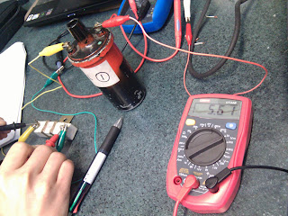
The RESISTANCE of the G Pickup Coil

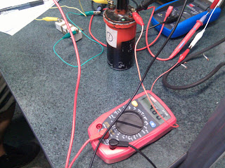
Testing the Distributor

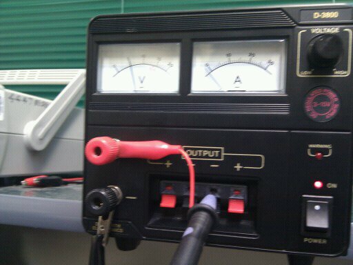
The distributor connected to the power source

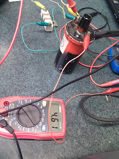
The voltage when the reluctor is away from the pickup coil

The voltage drops when the reluctor is at the pickup coil

The reading of the distributor on the oscilloscope when the shaft was turning

Testing the G Pickup Coil
 The reading of the NE Pickup Coil on the oscilloscope
=======================================================================
IGNITION COIL
The ignition coil is an electrical transformer.It contains both primary and secondary winding circuits.The coil primary windings contains 100-150 turns of heavy copper wire The wire must be insulated so that the voltage does not jump from loop to loop,short it out.If this happened,it could not create the primary magnetic field that is required.The primary circuit wire goes into the coil through the positive terminal,loops around the primary primary windings,then exits through the negative terminal.The coil secondary winding contains 15,000 - 30,000 turns of fine copper wire,which also must be insulated from each other.
The secondary windings sit inside the loops of the primary windings.To further increase the coils magnetic field,the windings are wrapped around a soft iron core.
To withstand the heat of the current flow,the coil is filled with oil which helps it cool.
The ignition coil is the heart of the ignition system.As current flows through the coil,a strong magnetic field builds up.When the current is shut off,the collapse of this magnetic field to the secondary windings induces a high voltage which is released through the large centre terminal.The voltage is then directed to the spark plugs through the distributor.
 Detailed picture of a coil

 Testing the Primary winding


 The voltage at the coil after it connected to the resistor
 Testing the voltage drop to the coil after it's connected to ballast resistor.
 Checking the voltage drop across the resistor
The ignition coil is an electrical transformer.It contains both primary and secondary winding circuits.The coil primary windings contains 100-150 turns of heavy copper wire The wire must be insulated so that the voltage does not jump from loop to loop,short it out.If this happened,it could not create the primary magnetic field that is required.The primary circuit wire goes into the coil through the positive terminal,loops around the primary primary windings,then exits through the negative terminal.The coil secondary winding contains 15,000 - 30,000 turns of fine copper wire,which also must be insulated from each other.
The secondary windings sit inside the loops of the primary windings.To further increase the coils magnetic field,the windings are wrapped around a soft iron core.
To withstand the heat of the current flow,the coil is filled with oil which helps it cool.
The ignition coil is the heart of the ignition system.As current flows through the coil,a strong magnetic field builds up.When the current is shut off,the collapse of this magnetic field to the secondary windings induces a high voltage which is released through the large centre terminal.The voltage is then directed to the spark plugs through the distributor.

Picture of the 2 coils we tested
Coil Specifications:
Coil#1 No=CIT-118 Coil#2 No=C6R-500
Coil#1 Voltage=12volts Coil#2 Voltage=12volts
Coil#1 Primary=1.0-1.3 ohms Coil#2 Primary=> Didn't have specs
Coil#1 Secondary=8.5-9.5 k/ohms Coil#2 Secondary=> Didn't have specs


Testing the secondary coil
Coil Test Results
Coil # 1 Primary=2.2 ohms
Coil # 1 Earth leakage test=No,it's a good coil
Coil # 2 Primary=2.3 ohms
Coil # 2 Secondary=8.0 k/ohms Serviceable?Coil is good.Can use it
Coil # 2 Earth leakage test=No leakage

Picture of the Ballast Resistor


Coil # 1 Secondary=9.3 k/ohms Serviceable?Coil is good.Can use it
All the sensors we saw and tested communicate.Most of the engine sensors are directly linked to the ECU,which receives the information and signals and processes it accordingly.And when a sensor is faulty.it sends a wrong or sometimes no signals to the ECU.This is when the ECU begins to assume what to do and the car malfunctions.
We saw most of the sensors required to run an engine.Now we have a better understanding of how everything works.And this will help in fault diagnosing
An ok start, but you got to watch your copy and paste! If you copy and paste you have to reference them. When its a copy and paste I cant mark that part of your blog because its not your own work. Next time make sure you reference other peoples work.
ReplyDeleteAnd just check your statement on the MAP sensor subject about pressure. It should be higher pressure when wot not lower.
ReplyDeletenice info...Great pictorial instructions .
ReplyDeleteCheap Radiators & Radiator Fans